Contents
IC Design and Verification Tools Developed by MICS
XMODEL: A Fast Behavioral Simulator for Analog/Mixed-Signal Systems
XMODEL is an extension to SystemVerilog simulators including Synopsys VCS, MentorGraphics ModelSim and Cadence NC-Verilog that enables accurate functional modeling and fast simulation of analog/mixed-signal systems. For high-speed links, XMODEL also provides powerful statistical simulation capability that can estimate extremely low bit-error rate (BER) of 10^-12 within a few minutes. XMODEL is now a commercial tool with a richer set of features and professional technical support. For more information, please visit http://www.scianalog.com. 
Global Convergence Analysis Toolkit (GCAT)
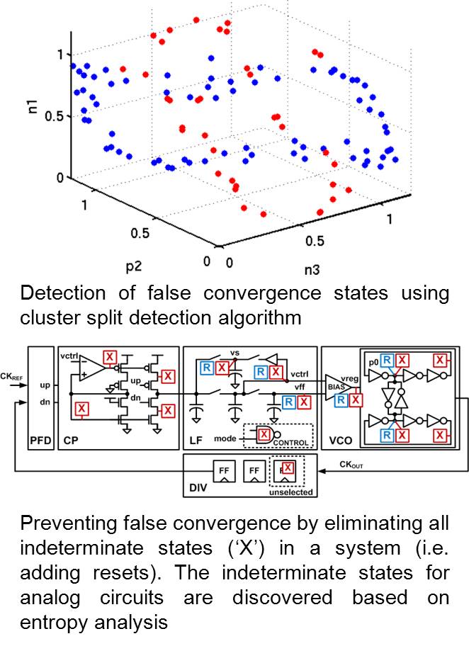
Many modern mixed-signal systems such as phase/delay-locked loops and DC-DC converters exhibit global convergence failures, also known as start-up failures. In other words, the system may have intermittent start-up failures due to its poorly initialized states. For instance, an oscillator may not start, a PLL may not converge to lock, and a DC-DC converter may fail to provide a correct voltage. To verify the existence of global convergence failures, GCAT offers two complementary approaches: the cluster split detection and indeterminate state (‘X’) elimination algorithms. For details, please visit this page. |
|
Global Convergence Checker for Oscillators (GCHECK)
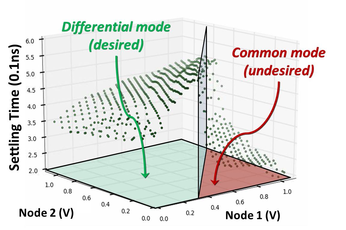
GCHECK is an automated verification tool that validate whether a ring oscillator always converges to the desired mode of operation regardless of the initial conditions and variability conditions. This is the first tool ever reported to address the global convergence failures in presence of variability. For more information, visit this page. |
|
Verilog-A Modules for Variable Domain Transformation
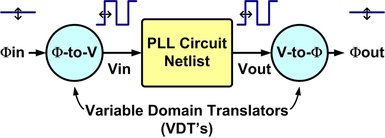
Variable Domain Transformation (VDT) is a useful concept to convert a seemingly nonlinear system in one variable domain into a linear system in another one. For instance, a phase-locked loop (PLL) that takes a large-signal clock input and produces a large-signal clock output may be viewed as a strongly-nonlinear system in voltage domain, but most PLL designers want to view it as a linear system in phase domain. With VDT modules, one can perform a periodic AC analysis (PAC) in variable domains other than voltage or current, such as phase, frequency, delay, and duty-cycle in order to simulate the AC transfer function of a phase-locked loop, delay-locked loop, duty-cycle adjuster.
Ref: J. Kim, K. D. Jones, M. A. Horowitz, ʺVariable Domain Transformation for Linear PAC Analysis of Mixed‐Signal Systems,ʺ ACM/IEEE Int’l Conf. on Computer‐Aided Design (ICCAD), Nov. 2007 (doi).
VDT module package: vdt.tar.gz

Cell-Based Design Flow for Analog/Mixed-Signal IC Developed by MICS
Cell-Based Design Flow
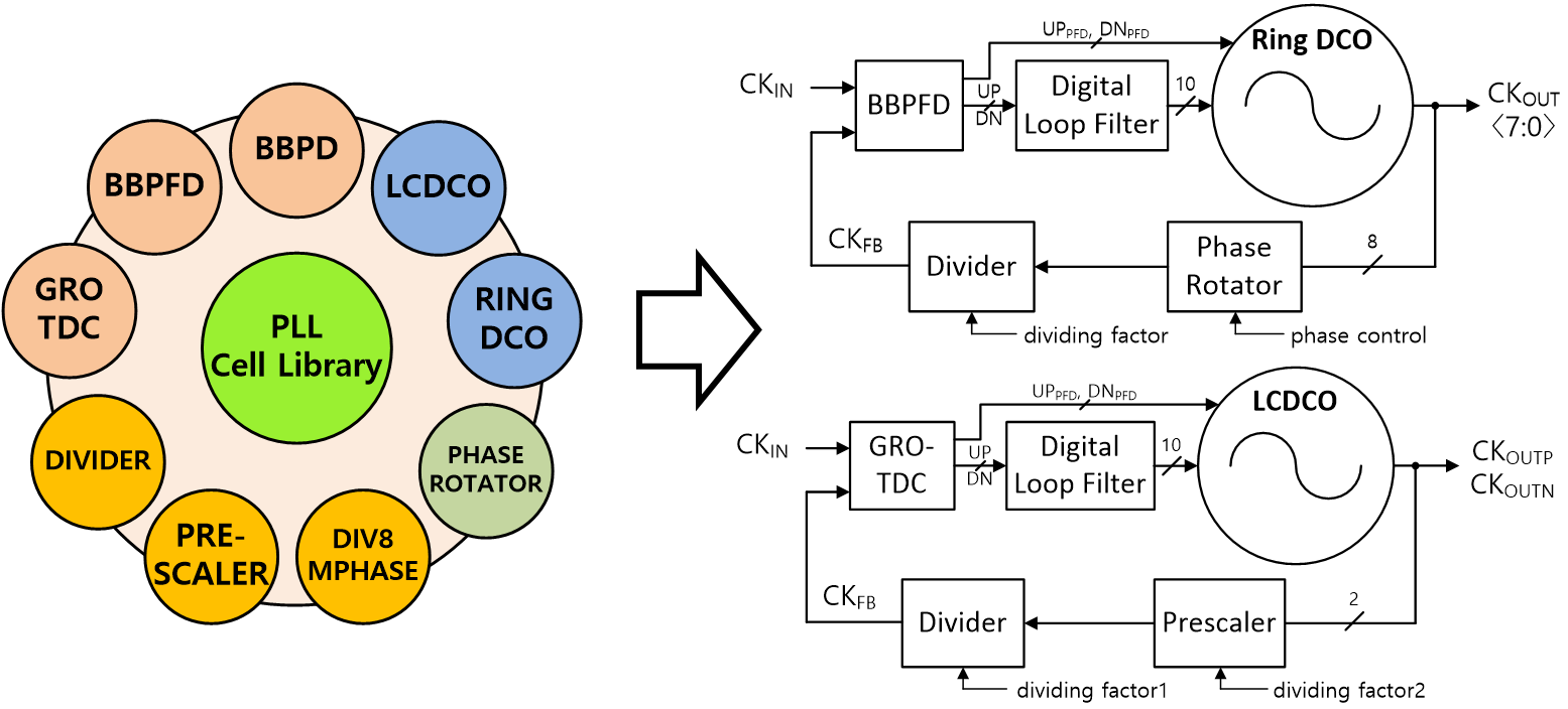
Cell-based design flow is a systematic design flow starting the design by verifying functionality of system model, and then turning it into circuits and layout. While traditional analog/mixed-signal circuit designers are suffering from high complexity of circuit system, this model-first design flow enables quick chip-level verification by XMODEL and automatic place-and-route (P&R) using IC Compiler and Custom Designer. With the aid of cell-based design flow, a person who may not aware of detail transistor-level circuit topologies can make PLLs without difficulty, only by model-level manipulation with provided analog cell library (ACL).
|
Tutorial Materials for Exercise
This material is an education-purpose package used in IDEC lecture on May 19-20th, 2016. This includes a digital phase-locked loop (PLL) example and ACL models to learn and exercise cell-based design flow for analog/mixed-signal IC. Also, it contains automated P&R scripts and libraries to experience IC Compiler/Custom Designer (ICCD) flow.
Please refer to the setup guide before you download the tutorial file package.
Setup guide: Easy_Setup_Guide.pdf
Tutorial file package: IDEC_CBDF.tar.gz
Lecture notes: lecture_notes.zip
(The setup guide and the lecture notes are appended to the tutorial file package: IDEC_CBDF/doc/)
|


